Today’s post is a short post on pedicle angulation. In general the pedicles have a “textbook” angle in how to align the screw to obtain the proper trajectory through the pedicle without violating the walls and possibly injuring nearby structures.
The angles are a general heuristic. However studying preoperative imaging can aid in refining plan for each patient. Sometimes the use of navigation makes the prep seem like overkill. However pre op planning is still helpful to ensure accuracy of navigation and in case navigation were to fail.
Part of pre op planning is determining whether to perform a percutaneous vs open approach. In the percutaneous approach, per op planning includes understanding the angulation of pedicles with respect to the fascia and skin. In percutaneous cases the skin and fascia act as a type of anchor or pivot point restricting the movement of the screw. The fascia is typically more restrictive than the skin and so is usually the culprit in restricting translation type movements which is why it acts as a fulcrum or pivot point. So docking on the “correct” bony starting point with a suboptimal fascial incision limits the amount of correction to the trajectory you can make with the Jamishidi while advancing through the pedicle. Take a look at the image 1 below.
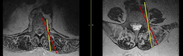
The red and yellow lines represent different trajectories based on the “correct” bony starting point, but with different fascial fulcrums. If the yellow line represents an incision based on lining up over the lateral edge of the cortex, then the screw trajectory will be more lateral in the vertebral body. The more “angled” the pedicle is with respect to the vertebral body, the more lateral the trajectory will be in the vertebral body. If you look at the left picture in image one the pedicles are less “angled” than the pedicles on the right image. Therefore there is a higher chance of lateral violation in the vertebral body in the more “angled pedicles.” Making an incision more lateral than the lateral border of the pedicle allows for a trajectory that better aims toward the center of the vertebral body. How lateral that incision is will depend on how angled the pedicles are with respect to the vertebral body.
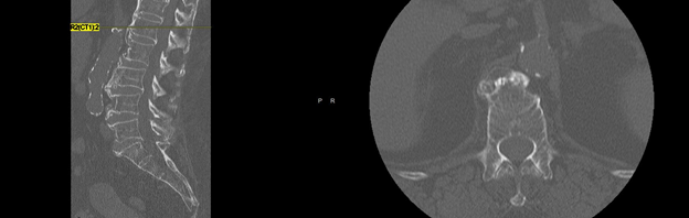
In general the lateral position of the incision with respect to the bony starting point favors visualization of instrument with respect to bony landmarks for guiding instruments. However the pedicles that are less angled can affect visualization, and if the instruments are radiopaque then using C arm for guidance can be dangerous. In image 2 below the preoperative CT shows pedicles that are pretty straight with respect to the vertebral body at L1.
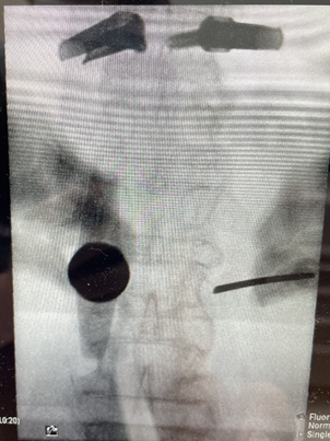
The pedicle angulation being straight can affect what types of instruments can be safely used which is why identifying this preoperatively can be useful for planning. In image 3 below the left L1 has an “all in one” system that advancing K wire just ahead of screw called Viper Prime to save steps. However the instrument blocks your view of the pedicle and if you were to angle the instrument out of the pedicle view, then it would affect your trajectory through the pedicle.
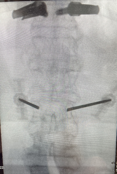
In image 4 below a Jamshidi is used to navigate through the straight pedicle since it does not obstruct the views needed when advancing through the pedicle.
Anyway morale of the story is pedicle angulation is an important pre op consideration when selecting instruments/systems to use.
